
You may graphically select items in order to view or modify part of the model or to print part of the results. When used in conjunction with the graphic editing features it allows you to quickly model and make modifications to the model. If used with results it allows you to view and print only the input or results that you want.
The elements that you see in the model views have two possible states; selected and unselected. By default, all items are selected, and therefore fully displayed. If you unselect any items, they are drawn in a gray or “ghosted” shade. To select or unselect an item simply click on it with the left mouse button. You may also use one of the selection tools below to select multiple items.
Note
The Selection Toolbar is the vertical toolbar located on the left side
of the screen. This toolbar is for selecting
Some of the tools are for one-time applications such as Select All. Other tools, such as Box Select, place you in a selection mode that remains active until you cancel it. The current mode is indicated by the mouse pointer and by the state of the button. While in a selection mode the button will stay depressed until you click it again, choose another button, or press the ESC key. You may have more than one model view open and may be in different modes in each view.
Note
Clicking Select All  and Unselect All
  tools will select or unselect all of the active
The Box Select  and Box Unselect
  tools allow you to draw a box around the items that
you wish to select or unselect.
tools allow you to draw a box around the items that
you wish to select or unselect.
The Polygon Select  and Polygon Unselect
  tools allow you to draw a polygon around the
items that you wish to select or unselect.
tools allow you to draw a polygon around the
items that you wish to select or unselect.
The Line Select  and Line Unselect
  tools allow you to draw a line through the
items that you wish to select or unselect. Any element the line crosses will be affected. This is useful when
choosing items between other items.
tools allow you to draw a line through the
items that you wish to select or unselect. Any element the line crosses will be affected. This is useful when
choosing items between other items.
The Invert Selection  button is used to invert the selected state of the model. When clicked, all selected items
are made unselected and all previously unselected items are made selected. For example, this
can be very useful when just a few items are to be selected in a large
model. Simply click on the desired items to unselect them, then click the
Invert Selection button to make
them selected and everything else unselected.
button is used to invert the selected state of the model. When clicked, all selected items
are made unselected and all previously unselected items are made selected. For example, this
can be very useful when just a few items are to be selected in a large
model. Simply click on the desired items to unselect them, then click the
Invert Selection button to make
them selected and everything else unselected.
The Criteria Selection  button allows you to select items based on a wide range
of criteria such as coordinates, labels and many other conditions. When
the Criteria Select button is clicked,
you will be presented with the Criteria Selection Dialog with options grouped by tabs across the top.
Each tab represents groups of criteria that you may use to refine your
selection.
button allows you to select items based on a wide range
of criteria such as coordinates, labels and many other conditions. When
the Criteria Select button is clicked,
you will be presented with the Criteria Selection Dialog with options grouped by tabs across the top.
Each tab represents groups of criteria that you may use to refine your
selection.
The options are numerous making it easy to quickly achieve complicated selections. This is a powerful tool so it is worth taking the time to experiment with the options so that you will know how to use it to your advantage. The various tabs in the dialog are described below.
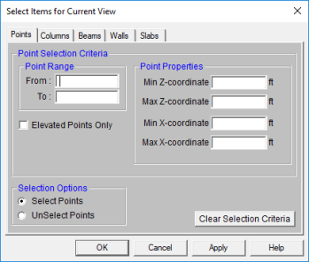
You may Select or Unselect Points as follows.
Point Range - You may specify a range of point labels. Specifying only one label selects just that one point.
Point Properties - You may specify a Min Horizontal, Max Horizontal, Min Vertical, and/or Max Vertical coordinate location.
Note
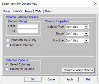
You may Select or Unselect Columns as follows.
Column Range – You may specify a range of Column labels. Specifying only one label selects just that one Column.
Column Properties – You may specify a Material Type, Shape, or Function when selecting columns.
Perimeter Selection – Checking this box will select only the perimeter columns of your building.
Note
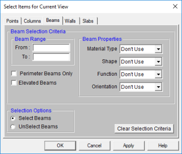
You may Select or Unselect beams as follows.
Beam Range – You may specify a range of Beam labels. Specifying only one label selects just that one beam.
Beam Properties – You may specify a Material Type, Shape, Function, or Orientation when selecting beams.
Perimeter Selection – Checking this box will select only the buildings perimeter beams.
Note
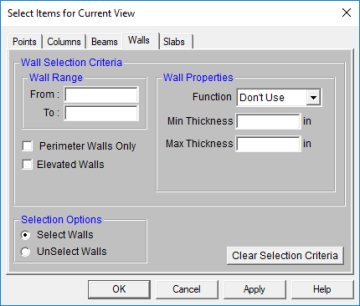
You may Select or Unselect walls as follows.
Wall Range – You may specify a range of Wall labels. Specifying only one label selects just that one wall.
Wall Properties – You may specify a Function or Thickness when selecting walls.
Perimeter Selection – Checking this box will select only the buildings perimeter walls.
Elevated Walls – Checking this box will select only the walls that have been modified using the Elevation Offset tool.
Note
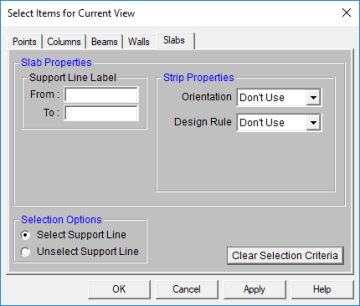
You may Select or Unselect slabs as follows.
Support Line Label – You may specify a range of Support Line labels. Specifying only one label selects just that one support line.
Strip Properties – You may specify an Orientation or Design Rule when selecting support lines.
Note
Click the Lock Unselected  button to
cause all currently unselected items to stay unselected and be visually removed from the current model view. This
is useful when you are editing or printing a portion of a model and need to clear the model view of all items not involved.
button to
cause all currently unselected items to stay unselected and be visually removed from the current model view. This
is useful when you are editing or printing a portion of a model and need to clear the model view of all items not involved.
To Unlock the unselected members in the model view, click the Unlock Unselected  button and the unselected items that were previously "removed" from the model view will be returned to the view in the unselected state.
In many spreadsheets, both Data Entry and Results, you can select rows on the spreadsheet and use the right-click menu to select the Select Marked Lines in Current View or Unselect Marked Lines in the Current View options. This will graphically select or unselect the items corresponding to the selected rows in the top most model view window. This is very useful for highlighting failing members in a spreadsheet and then having them graphically selected in a model view to see where the problems are.
You can save and recall various selection states for a model. If
the model is altered after a selection state has been saved, the saved
selection state will also be altered. Any new items (
To save a selection state, click the Save Selection State  button on the Selection Toolbar.
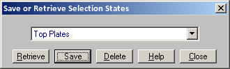
Click the Save button and provide a name for the saved selection. You can have up to 15 different saved selections in a model. To retrieve a saved selection, choose the selection state from the drop down list and click the Retrieve button. To delete a saved selection, choose the selection state from the drop down list and click the Delete button.